Chapter 2. The Transport Layer: TCP, UDP, and SCTP
Introduction
This chapter focuses on the transport layer: TCP, UDP, and Stream Control Transmission Protocol (SCTP). UDP is a simple, unreliable datagram protocol, while TCP is a sophisticated, reliable byte-stream protocol. SCTP is similar to TCP as a reliable transport protocol, but it also provides message boundaries, transport-level support for multihoming, and a way to minimize head-of-line blocking.
The Big Picture
Overview of TCP/IP protocols:
| Protocol | Description |
|---|---|
| IPv4 | Internet Protocol version 4. IPv4 uses 32-bit addresses and provides packet delivery service for TCP, UDP, SCTP, ICMP, and IGMP. |
| IPv6 | Internet Protocol version 6. IPv6 uses 128-bit addresses. |
| TCP | Transmission Control Protocol. TCP is a connection-oriented protocol that provides a reliable, full-duplex byte stream to its users |
| UDP | User Datagram Protocol. UDP is a connectionless protocol, and UDP sockets are an example of datagram sockets. |
| SCTP | Stream Control Transmission Protocol. SCTP is a connection-oriented protocol that provides a reliable full-duplex association |
| ICMP | Internet Control Message Protocol. ICMP handles error and control information between routers and hosts. |
| IGMP | Internet Group Management Protocol. IGMP is used with multicasting. |
| ARP | Address Resolution Protocol. ARP maps an IPv4 address into a hardware address (such as an Ethernet address). ARP is normally used on broadcast networks such as Ethernet, token ring, and FDDI, and is not needed on point-to-point networks. |
| RARP | Reverse Address Resolution Protocol. RARP maps a hardware address into an IPv4 address. It is sometimes used when a diskless node is booting. |
| ICMPv6 | Internet Control Message Protocol version 6. ICMPv6 combines the functionality of ICMPv4, IGMP, and ARP. |
| BPF | BSD packet filter. This interface provides access to the datalink layer. It is normally found on Berkeley-derived kernels. |
| DLPI | Datalink provider interface. |
User Datagram Protocol (UDP)
- Lack of reliability
- Each UDP datagram has a length
- Connectionless service
Transmission Control Protocol (TCP)
- Connection: TCP provides connections between clients and servers. A TCP client establishes a connection with a server, exchanges data across the connection, and then terminates the connection.
- Reliability: TCP requires acknowledgment when sending data. If an acknowledgment is not received, TCP automatically retransmits the data and waits a longer amount of time.
- Round-trip time (RTT): TCP estimates RTT between a client and server dynamically so that it knows how long to wait for an acknowledgment.
- Sequencing: TCP associates a sequence number with every byte (segment, unit of data that TCP passes to IP.) it sends. TCP reorders out-of-order segments and discards duplicate segments.
- Flow control
- Full-duplex: an application can send and receive data in both directions on a given connection at any time.
Stream Control Transmission Protocol (SCTP)
Like TCP, SCTP provides reliability, sequencing, flow control, and full-duplex data transfer.
Unlike TCP, SCTP provides:
- Association instead of "connection": An association refers to a communication between two systems, which may involve more than two addresses due to multihoming.
- Message-oriented: provides sequenced delivery of individual records. Like UDP, the length of a record written by the sender is passed to the receiving application.
- Multihoming: allows a single SCTP endpoint to support multiple IP addresses. This feature can provide increased robustness against network failure.
TCP Connection Establishment and Termination
Three-Way Handshake
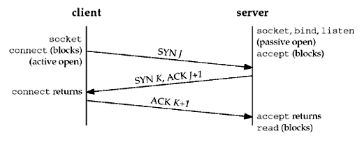
- Server: passive open, by calling
socket,bind, andlisten - Client: active open, by calling
connect. The client TCP to send a "synchronize" (SYN) segment with no data but it contains client's initial sequence number for the data to be sent on the connection. - Server: acknowledges (ACK) client's SYN. The server sends its SYN and the ACK of the client's SYN in a single segment which also contains its own SYN containing the initial sequence number for the data to be sent on the connection.
- Client: acknowledges the server's SYN.
The client's initial sequence number as J and the server's initial sequence number as K. The acknowledgment number in an ACK is the next expected sequence number for the end sending the ACK. Since a SYN occupies one byte of the sequence number space, the acknowledgment number in the ACK of each SYN is the initial sequence number plus one.
TCP Options
- MSS option. The TCP sending the SYN announces its maximum segment size (the maximum amount of data that it is willing to accept in each TCP segment) on this connection. The sending TCP uses the receiver's MSS value as the maximum size of a segment that it sends. Section 7.9 discusses how to fetch and set this TCP option with the
TCP_MAXSEGsocket option. - Window scale option. The maximum window that the TCP can advertise to the other is 65,535, because the corresponding field in the TCP header occupies 16 bits. However, high-speed connections, common in today's Internet, or long delay paths (satellite links) require a larger window to obtain the maximum throughput possible. This newer option specifies that the advertised window in the TCP header must be scaled (left-shifted) by 0–14 bits, providing a maximum window of almost one gigabyte (65,535 x 214). Both end-systems must support this option for the window scale to be used on a connection. Section 7.5 discusses how to affect this option with the
SO_RCVBUFsocket option.- To provide interoperability with older implementations that do not support this option, TCP can send the option with its SYN as part of an active open, but it can scale its windows only if the other end also sends the option with its SYN. Similarly, the server's TCP can send this option only if it receives the option with the client's SYN. Implementations ignore options that they do not understand.
- Timestamp option. This option is needed for high-speed connections to prevent possible data corruption caused by old, delayed, or duplicated segments. Since it is a newer option, it is negotiated similarly to the window scale option.
These common options are supported by most implementations. The latter two are sometimes called the "RFC 1323 options", or "long fat pipe options", since a network with either a high bandwidth or a long delay is called a long fat pipe.
TCP Connection Termination

It takes four segments to terminate a connection:
- One end calls
closefirst by sending a FIN segment to mean it is finished sending data. This is called active close. - The other end that receives the FIN performs the passive close. The received FIN is acknowledged by TCP (sending an ACK segment). The receipt of the FIN is also passed to the application as an end-of-file.
- Sometime later, the application that received the end-of-file will close its socket. This causes its TCP to send a FIN.
- The TCP on the system that receives this final FIN (the end that did the active close) acknowledges the FIN
A FIN occupies one byte of sequence number space just like a SYN. Therefore, the ACK of each FIN is the sequence number of the FIN plus one.
TCP State Transition Diagram
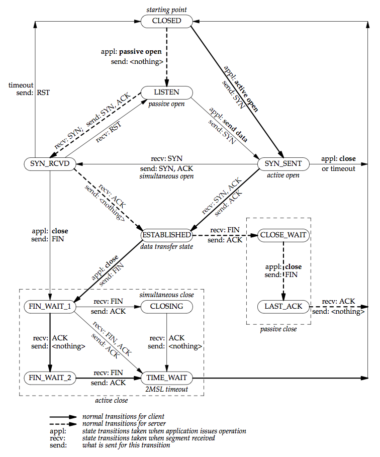
There are 11 different states defined for a connection and the rules of TCP dictate the transitions from one state to another, based on the current state and the segment received in that state.
Watching the Packets
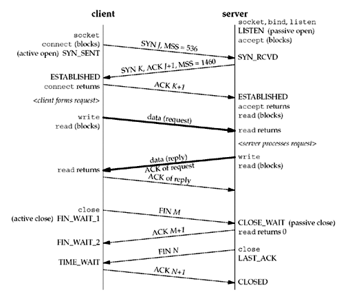
The client in this example announces an MSS of 536 (minimum reassembly buffer size) and the server announces an MSS of 1,460 (typical for IPv4 on an Ethernet). It is okay for the MSS to be different in each direction. The acknowledgment of the client's request is sent with the server's reply. This is called piggybacking and will normally happen when the time it takes the server to process the request and generate the reply is less than around 200 ms.
With TCP, there would be eight segments of overhead. If UDP was used, only two packets would be exchanged.
- UDP removes all the reliability that TCP provides to the application.
- UDP avoids the overhead of TCP connection establishment and connection termination.
TIME_WAIT State
The end that performs the active close goes through the TIME_WAIT state. The duration that this endpoint remains in the TIME_WAIT state is twice the maximum segment lifetime (MSL), sometimes called 2MSL, which is between 1 and 4 minutes. The MSL is the maximum amount of time that any given IP datagram can live in a network. The IPv4 TTL field IPv6 hop limit field have a maximum value 255. The assumption is made that a packet with the maximum hop limit of 255 cannot exist in a network for more than MSL seconds. [p43]
TCP must handle lost duplicates (or wandering duplicate).
There are two reasons for the TIME_WAIT state:
- To implement TCP's full-duplex connection termination reliably. If TCP is performing all the work necessary to terminate both directions of data flow cleanly for a connection (its full-duplex close), then it must correctly handle the loss of any of these four segments.
- To allow old duplicate segments to expire in the network. When we successfully establish a TCP connection, all old duplicates from previous incarnations of the connection have expired in the network.
Port Numbers
All three transport layers (UDP, SCTP and TCP) use 16-bit integer port numbers to differentiate between processes.
- The well-known ports: 0 through 1023.
- The registered ports: 1024 through 49151
- The dynamic ports or private ports, 49152 through 65535. Also called ephemeral ports.
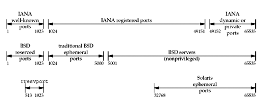
Some notes from the figure above:
- On Unix, reserved port is any port less than 1024. These ports can only be assigned to a socket by an appropriately privileged process. All the IANA well-known ports are reserved ports. The server allocating this port must have superuser privileges when it starts.
- Historically, Berkeley-derived implementations (starting with 4.3BSD) have allocated ephemeral ports in the range 1024–5000. Many newer systems allocate ephemeral ports differently to provide more ephemeral ports, either using the IANA-defined ephemeral range or a larger range
Socket Pair
- Socket pair: the four-tuple that defines the two endpoints of a TCP connection: the local IP address, local port, foreign IP address, and foreign port. A socket pair uniquely identifies every TCP connection on a network.
- Socket: two values (an IP address and a port number) that identify each endpoint.
TCP Port Numbers and Concurrent Servers
[p52-55]
Buffer Sizes and Limitations
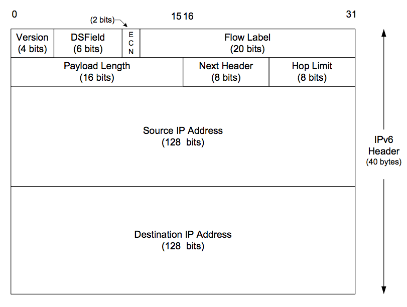
Figures: IPv4 Header, IPv6 Header
- Maximum size of an IPv4 datagram: 65,535 bytes (including the header), because of the 16-bit total length field.
- Maximum size of an IPv6 datagram: 65,575 bytes (including the 40-byte IPv6 header), because of the 16-bit payload length field. IPv6 has a jumbo payload option, which extends the payload length field to 32 bits, but this option is supported only on datalinks with a maximum transmission unit (MTU) that exceeds 65,535.
- MTU (maximum transmission unit): dictated by the hardware. Ethernet MTU is 1,500 bytes; Point-to-point links have a configurable MTU.
- Minimum link MTU for IPv4: 68 bytes. This permits a maximum-sized IPv4 header (20 bytes of fixed header, 40 bytes of options) and minimum-sized fragment (the fragment offset is in units of 8 bytes) [errata]
- Minimum link MTU for IPv6: 1,280 bytes.
- Path MTU: smallest MTU in the path between two hosts. Today, the Ethernet MTU of 1,500 bytes is often the path MTU. The path MTU need not be the same in both directions between any two hosts because routing in the Internet is often asymmetric.
- Fragmentation is performed by both IPv4 and IPv6 when the size of an IP datagram to be sent out an interface exceeds the link MTU. The fragments are not normally reassembled until they reach the final destination.
- IPv4: hosts perform fragmentation on datagrams that they generate and routers perform fragmentation on datagrams that they forward
- IPv6: only hosts perform fragmentation on datagrams that they generate; routers do not fragment datagrams that they are forwarding
- IPv4 header contains fields to handle fragmentation. IPv6 contains an option header with the fragmentation information.
- "Don't Fragment" (DF) bit in IPv4 header specifies that this datagram must not be fragmented, either by the sending host or by any router. A router that receives an IPv4 datagram with the DF bit set whose size exceeds the outgoing link's MTU generates an ICMPv4 "destination unreachable, fragmentation needed but DF bit set" error message.
- Since IPv6 routers do not perform fragmentation, there is an implied DF bit with every IPv6 datagram. When an IPv6 router receives a datagram whose size exceeds the outgoing link's MTU, it generates an ICMPv6 "packet too big" error message
- Path MTU discovery uses IPv4 DF bit and its implied IPv6 counterpart. Path MTU discovery is optional with IPv4, but IPv6 implementations all either support path MTU discovery or always send using the minimum MTU. [p55]
- Minimum reassembly buffer size: the minimum datagram size that we are guaranteed any implementation must support.
- IPv4: 576 bytes. We have no idea whether a given destination can accept a 577-byte datagram or not. Therefore, many IPv4 applications that use UDP (e.g., DNS, RIP, TFTP, BOOTP, SNMP) prevent applications from generating IP datagrams that exceed this size.
- IPv6: 1,500 bytes
- TCP has a maximum segment size (MSS) that announces to the peer TCP the maximum amount of TCP data that the peer can send per segment. We saw the MSS option on the SYN segments in Figure 2.5. The goal of the MSS is to tell the peer the actual value of the reassembly buffer size and to try to avoid fragmentation. The MSS is often set to the interface MTU minus the fixed sizes of the IP and TCP headers. On an Ethernet using IPv4, this would be 1,460, and on an Ethernet using IPv6, this would be 1,440. (The TCP header is 20 bytes for both, but the IPv4 header is 20 bytes and the IPv6 header is 40 bytes.)
- IPv4: The MSS value in the TCP MSS option is a 16-bit field, limiting the value to 65,535. The maximum amount of TCP data in an IPv4 datagram is 65,495 (65,535 minus the 20-byte IPv4 header and minus the 20-byte TCP header).
- IPv6: the maximum amount of TCP data in an IPv6 datagram without the jumbo payload option is 65,515 (65,535 minus the 20-byte TCP header). The MSS value of 65,535 is considered a special case that designates "infinity." This value is used only if the jumbo payload option is being used, which requires an MTU that exceeds 65,535.
TCP Output
The following figure shows what happens when an application writes to a TCP socket:
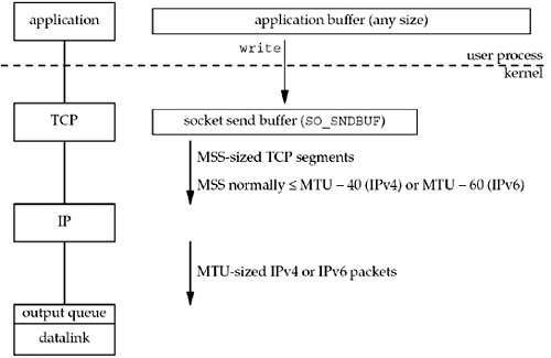
Every TCP socket has a send buffer and we can change the size of this buffer with the SO_SNDBUF socket option. When an application calls write, the kernel copies all the data from the application buffer into the socket send buffer. If there is insufficient room in the socket buffer for all the application's data, the process is put to sleep. This assumes the normal default of a blocking socket. The kernel will not return from the write until the final byte in the application buffer has been copied into the socket send buffer. Therefore, the successful return from a write to a TCP socket only tells us that we can reuse our application buffer. It does not tell us that either the peer TCP has received the data or that the peer application has received the data. This is discussed with SO_LINGER socket option.
TCP takes the data in the socket send buffer and sends it to the peer TCP. The peer TCP must acknowledge the data, and as the ACKs arrive from the peer, only then can our TCP discard the acknowledged data from the socket send buffer. TCP must keep a copy of our data until it is acknowledged by the peer.
TCP sends the data to IP in MSS-sized or smaller chunks, prepending its TCP header to each segment, where the MSS is the value announced by the peer, or 536 if the peer did not send an MSS option. IP prepends its header, searches the routing table for the destination IP address, and passes the datagram to the appropriate datalink. IP might perform fragmentation before passing the datagram to the datalink, but one goal of the MSS option is to try to avoid fragmentation and newer implementations also use path MTU discovery. Each datalink has an output queue, and if this queue is full, the packet is discarded and an error is returned up the protocol stack [p58]
UDP Output
The following figure shows what happens when an application writes data to a UDP socket:
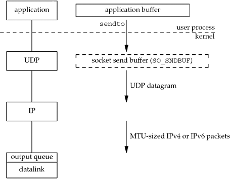
UDP socket doesn't have a socket send buffer, since it does not need to keep a copy of the application's data. It has a send buffer size (which we can change with the SO_SNDBUF socket option), but this is simply an upper limit on the maximum-sized UDP datagram that can be written to the socket. If an application writes a datagram larger than the socket send buffer size, EMSGSIZE is returned.
UDP simply prepends its 8-byte header and passes the datagram to IP. IP determines the outgoing interface by performing the routing function, and then either adds the datagram to the datalink output queue (if it fits within the MTU) or fragments the datagram and adds each fragment to the datalink output queue (see UDP and IP Fragmentation in TCPv1). If a UDP application sends large datagrams, there is a much higher probability of (IP) fragmentation than with TCP.